

First, a quick overview of what this feature actually is. Most weldors are familiar with balance and frequency adjustment. Balance is the percentage of time that the machine is on the EN or EP side of the wave during each cycle. Frequency is the number of cycles per second that the machine is cycling. So if you are running 75% EN balance and 120 Hz, the machine is spending 75% of the the time on the electrode negative side of the cycle and 25% of the time on the electrode positive side of the cycle and it's switching 120 times per second. By introducing independently adjustable EN and EP amperage, you can dial in the amps on each side of the wave. For instance, you might run 125 amps on the EN side and 100 amps on the EP side. The common approach and what most of the machine manufacturers recommend is running higher EN amps than EP amps to put more heat into the part for deeper penetration and less heat coming back into the tungsten.
When I got the expansion for my machine, I started off by going with Miller's suggestion. I started off with a ratio of 1.5/1.0 EN/EP. In other words, the EN amperage was 1.5 times greater than the EP amperage. The results were not what I was expecting or hoping for. I found I had to turn my balance down to get enough cleaning and that resulted in more tungsten degradation than I was used to (I was running a 3/32" 2% lanthanated). It got me thinking about what is actually going on during the EP cycle and what is really doing the cleaning. Did it have more to do with the amperage or the % balance? I started experimenting with running the EP amperage higher than the EN amperage to understand if it improved cleaning. I was really surprised to find that for my application, the amperage on the EP cycle played a more significant role in cleaning than the time (balance did). I started pushing the limits a bit, and went as high as a 1.0/1.5 EN/EP ratio and a balance of 85-90% EN. Yes, the EP amps were 1.5 times greater than the EN amps. I was able to go down to a 1/16" 2% lanthanated electrode ground to a sharp point. The resulting control was really shocking. It's been as close to feeling like running DC on steel as I've been able to dial in yet. I also found my restarts looked a little nicer and the etching zone was narrower and more faint. In my business, weld aesthetics sells. It really matters. I'm really happy with how the finished product is looking.
Here, I have my EP amps set at 280 amps and my EN amps set at 195 amps. Wave shape was advanced square wave for both EN and EP. My balance was set at 80-85% EN depending on the joint. Welding the sides of the tube goes a little nicer with a bit more cleaning compared to the deeper angles. Frequency was 250 Hz. Running a CK20 torch with a gas lens and #8 cup running at 18 CFH.
Here's the initial prep on the tungsten.
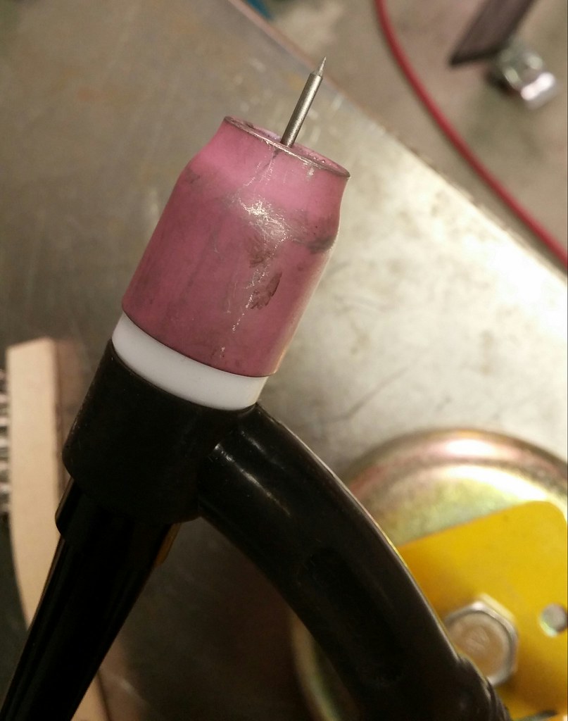
1/16" 2% lanthanated initial prep by Zanconato Custom Cycles, on Flickr
Here's the tungsten after tacking the two front triangles.

1/16" 2% lanthanated after tacking by Zanconato Custom Cycles, on Flickr
Tacked triangles.
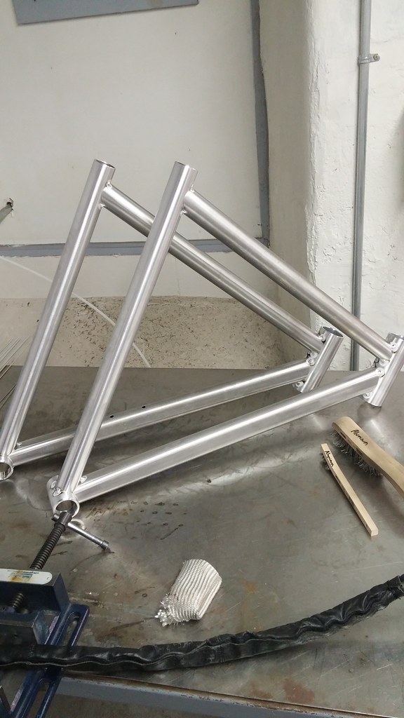
tacked by Zanconato Custom Cycles, on Flickr
Tungsten after welding out the front triangles. Now granted, this isn't a ton of welding. But I think it help up amazingly well.
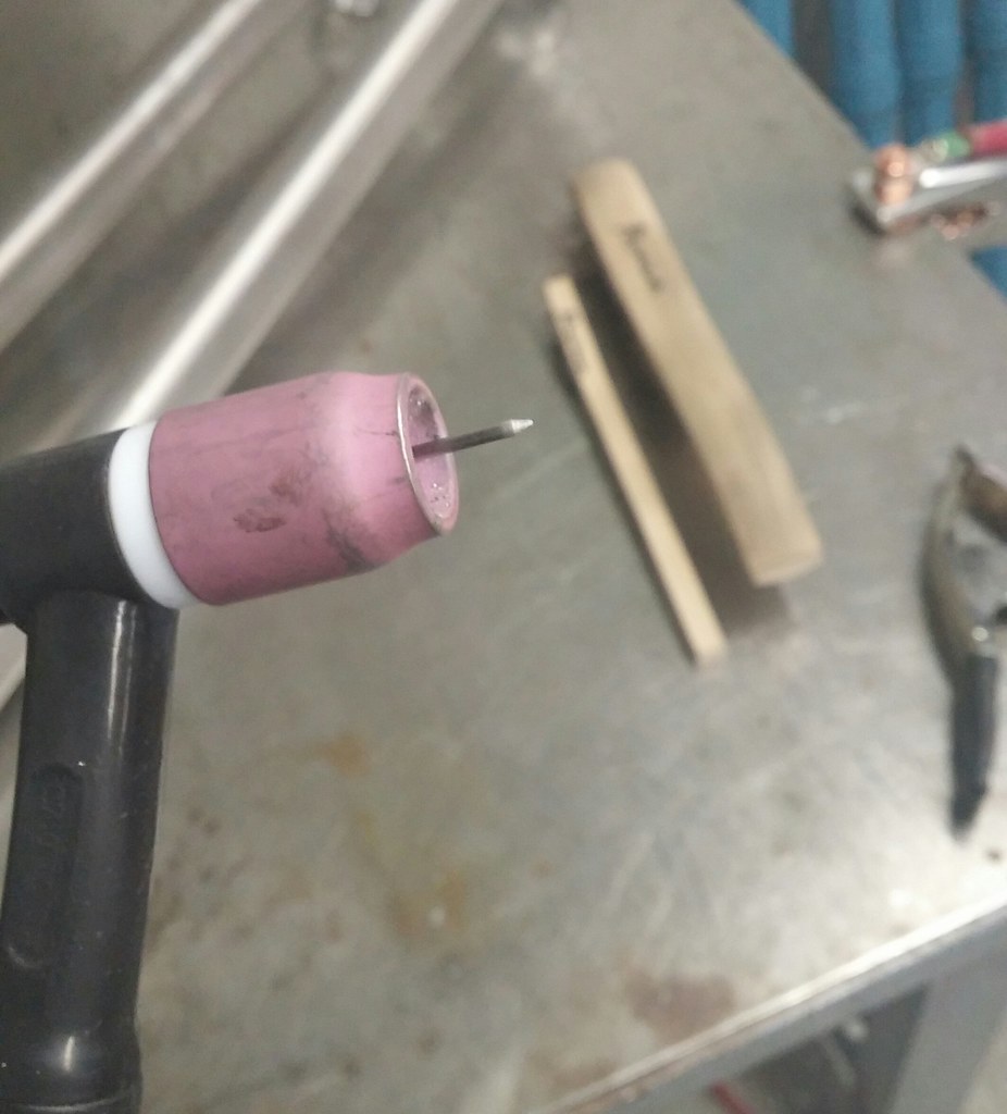
1/16" 2% lanthanated after welding by Zanconato Custom Cycles, on Flickr
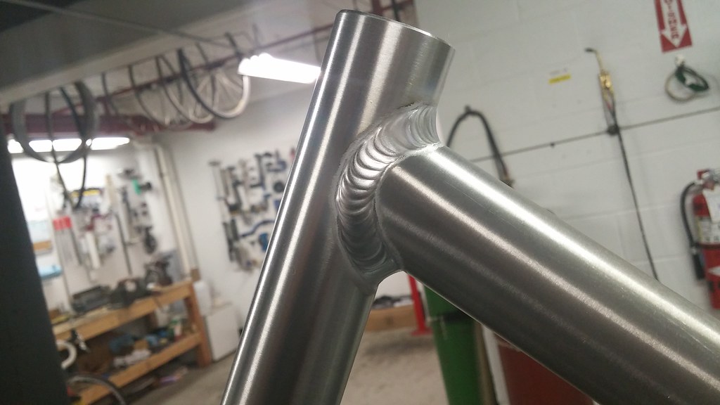
Seat cluster by Zanconato Custom Cycles, on Flickr

Bottom bracket by Zanconato Custom Cycles, on Flickr
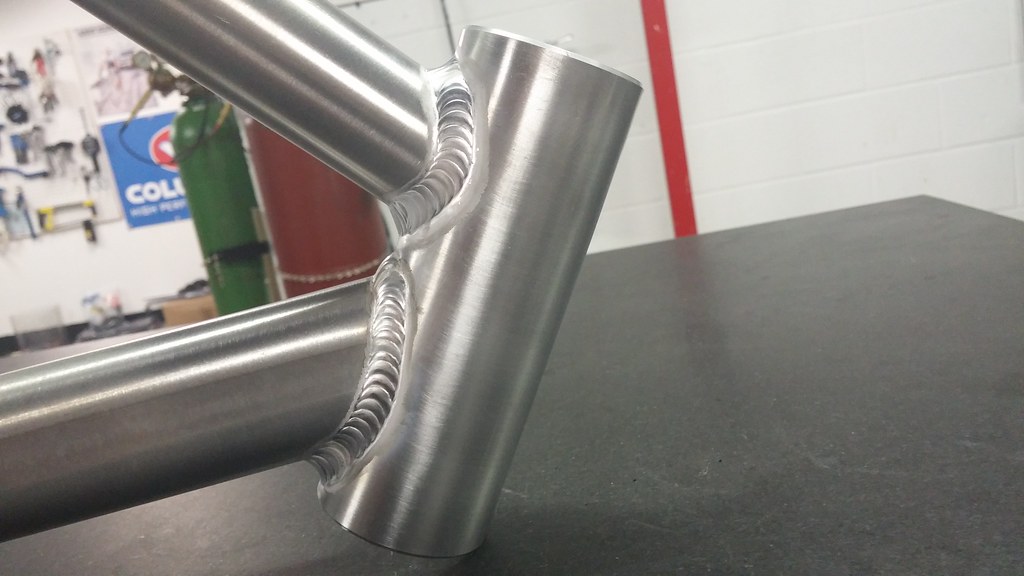
Head tube by Zanconato Custom Cycles, on Flickr
For reference, the head tube is 2" OD x 0.145" wall. The threaded bottom bracket shell is 1.75" OD by 0.160" wall. The three main tubes vary between 0.052" and 0.074" wall. Material is 7005 aluminum. Filler was 5183.
If you've made it this far, I hope you found the info useful. I'm going to keep experimenting with wave shape and I'll put up more info if people are interested.
I keep coming back to what Dave Powelson has typed quite a few times. There are an infinite number of ways to set up these inverters. I'll add to not get boxed in by the recommendations. Experiment a lot!